Overview
Sonus/Ribbon Cloud Link is an integrated appliance that combines Sonus/Ribbon’s SBC with embedded Skype for Business Cloud Connector Edition software (CCE). Cloud Link comes as a Windows Hyper-V Server that resides on the hardware of SBC. This server hosts the 4 VMs of CCE.
In this article I will explain how to deploy Cloud Link in some details. The article is based on real word implementation that is used in production.
What is missing is from this article is the outing and Transformation on Sonus/Ribbon SBC which will be covered in another article
All the snapshot has been taken on SBC 1000. The steps are exactly similar on SBC 2000.
Firewall Ports and Settings
Internal Firewall:
The following firewall ports required between Mediation Server VM IP and Internal clients (Internal network)
| Source IP |
Destination IP
|
Source Port
|
Destination Port
|
| Cloud Connector Mediation component |
Internal clients |
TCP 49 152 – 57 500* |
TCP 50,000-50,019 (Optional) |
| Cloud Connector Mediation component |
Internal clients |
UDP 49 152 – 57 500* |
UDP 50,000-50,019 |
| Internal clients |
Cloud Connector Mediation component |
TCP 50,000-50,019 |
TCP 49 152 – 57 500* |
| Internal clients |
Cloud Connector Mediation component |
UDP 50,000-50,019 |
UDP 49 152 -57 500* |
External Firewall:
The following firewall ports required between Edge Server VM external IP and Internet
| Source IP |
Destination IP
|
Source Port
|
Destination Port
|
| Any |
Cloud Connector Edge External Interface |
Any |
TCP 5061 |
| Cloud Connector Edge External Interface |
Any |
Any |
TCP 5061 |
| Cloud Connector Edge External Interface |
Any |
Any |
TCP 80 |
| Cloud Connector Edge External Interface |
Any |
Any |
UDP 53 |
| Cloud Connector Edge External Interface |
Any |
Any |
TCP 53 |
| Cloud Connector Edge External Interface |
Any |
TCP 50,000-59,999 |
Any |
| Cloud Connector Edge External Interface |
Any |
UDP 3478 |
Any |
| Cloud Connector Edge External Interface |
Any |
UDP 50,000-59,999 |
Any |
| Any |
Cloud Connector Edge External Interface |
Any |
TCP 443 |
| Any |
Cloud Connector Edge External Interface |
Any |
TCP 50,000-59,999 |
| Any |
Cloud Connector Edge External Interface |
Any |
UDP 3478 |
| Any |
Cloud Connector Edge External Interface |
Any |
UDP 50,000 – 59,999 |
Host Firewall Rules
The host ASM (Windows Hyper-V Server) which is the physical server. Requires access to the internet in order for it download the VMs and to configure Office 365 settings
| Source IP |
Destination IP |
Source Port |
Destination Port |
| ASM |
Any |
Any |
TCP 53 |
| ASM |
Any |
Any |
TCP 80 |
| ASM |
Any |
Any |
TCP 443 |
SBC 1000 Initial Setup
In this section, I will explain how to perform the Initial setup of Sonus (Ribbon) SBC 1000.
Connect your computer to the second Ethernet port of SBC 1000 and wait until the it finishes booting up (about 5 minutes) and make sure that you have got an IP address from the range 192.168.192.2. The SBC is providing a temporary DHCP to give your PC an IP address for easier config. This DHCP will not be enabled after completing the Initial Setup.

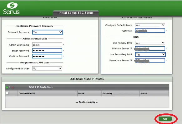
The following two pictures shows a typical configuration. The changed options are marked with thicker rectangles (the web interface automatically adds these rectangles)
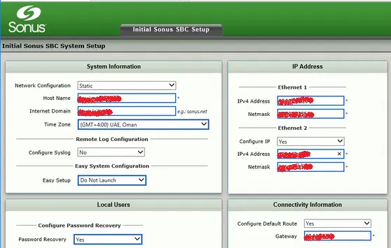
Note that the “Admin User Name” and Password will be used to access the Gateway only and not the ASM (Hyper-V Host)
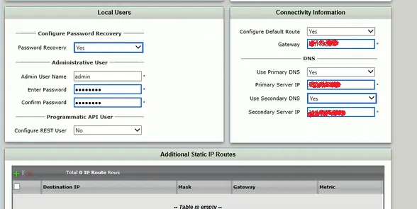
The IP address you have provided will be used for the Ethernet Interface number 1 in the front panel
In the above configuration, we have also configured the IP address of the Ethernet Interface number 2 to be same as the one used during the initial configuration. This would help us to access the gateway on Ethernet Interface 2 with its default IP in case we have a problem with the first interface, or we have forgot its IP.
For the primary DNS, put the IP address of CCE’s Domain Controller VM that you are going to build later.
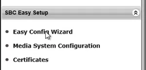
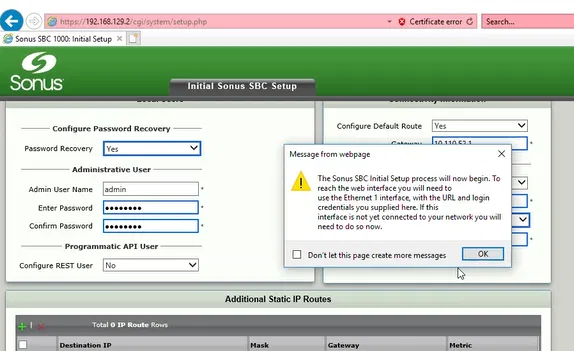
Note that we select the option “Don Not Launch” for the “Easy Setup”
Click on OK
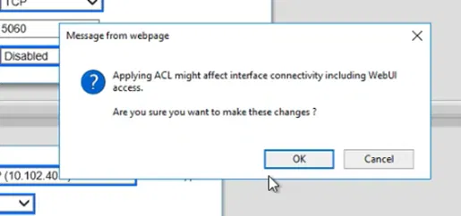
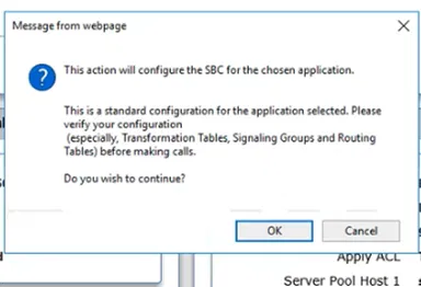
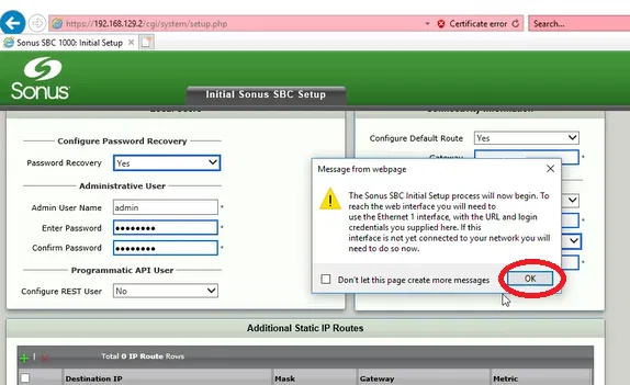
Read the Dialog Box and click on OK

Connect the first Ethernet interface to the network (if you have not already done that)
Enter the IP address of the gateway in the browser, it will show the following page only the first time you connect to the gateway on this browser using this address
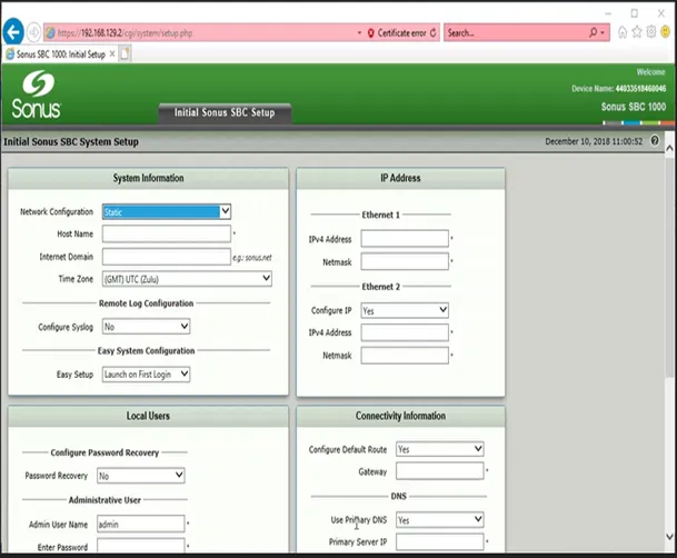
Click on Enter, it will take you to the logon screen

Enter the User ID and the Password you have supplied during the initial setup and click on Login

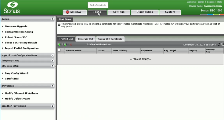
You will be taken to Tasks Page/Tab, unless you have selected to “Launch Easy Setup” in the initial setup step. On that case, you simply cancel the “Easy Setup Wizard”

ASM Config tab
In this step, we will configure the ASM (CCE Hyper-V Host) which is the physical Windows server that is attached to SBC 1000 Gateway
To start the process of configuring CCE
On the Tasks Tab, expand “Office 365 Cloud Connector Edition” menu and click on Setup

Configure the IP address, Subnet Mask and Gateway of CCE Host

Don’t forget to enable Remote Desktop on

Installing ASM update
Go to Settings Tab
Expand “Application Solution Module” menu
Select “Install ASM Update”
And click on Choose File

Select the file (downloaded from Ribbon) and click Open

Click on OK

Click OK on the Dialog Box

Watch the progress of installing the file on “Current Activity Status”

In the current case, we have selected a file that updates “SBC Communication Services” component which is responsible for the communication between ASM (that hosts the CCE Host) and the gateway itself.
This component is required to be updated before updating the gateway. Both “SBC Communication Services” and the gateway should be the same version, but “SBC Communication Services” needs to be updated before the gateway

Upgrading the firmware of SBC
On the Tasks Tab, under System menu, select Firmware Upgrade

If this is the first time you are doing the update, It will force you to take backup of the SBC
(you have the option to provide a Passphrase to protect the Backup file)
Click on Backup

You can save the backup file to a specific location if you want

Now the option to select a Firmware file is enabled (it is not enabled if you are trying to update the firmware for the first time until you take a backup)
Click on Brows

Select the Firmware file and click on Open

Click on Upgrade button

Click on OK on the dialog box after reading it

The process of upgrading the firmware now started

After the upgrade is completed, a restart will be automatically performed
Logon and go to System Tab and then go to “Abound Sonus SBC”
If the upgrade is successful, you will see the Software Version is changes

Notice that in our case, we upgraded the firmware to version 8 which shows the new black them of Ribbon
Generate CSR Tab
Click on Generate CSR Tab and fill in the information for the certificate
Certificate Requirements:
To meet the certificate requirements, you will need to decide between the following options and provide the Subject Name (SN) and Subject Alternative Name (SAN) for the certificate.
Option 1:
The Common Name should be the public name of the edge server which could be AccessEdge.example.com
The Subject Alternative Name DNS should be the public name of the edge server, followed by comma followed by sip.DomainName.com
Example:
SN = AccessEdge.example.com,
SAN = sip.example.com,
SAN = AccessEdge.example.com
Option 2 (using wild card certificate):
The Common Name should be the public name of the edge server which could be AccessEdge.example.com
The Subject Alternative Name DNS should be sip.example.com, followed by comma followed by *.DomainName.com
Example:
SN = AccessEdge.sipdomain.com,
SAN = sip.sipdomain.com,
SAN = *.sipdomain.com
Adding additional name to the existing wild card certificate is usually easy with Public Certificate providers
Fill the remaining fields correctly and make sure that you have selected Key Length as 2048

Click on OK
And the CSR will be generated

Copy the CSR and request the public certificate
Importing Public Certificate
This certificate will be assigned to the external interface of Edge VM of CCE. It will be used during the communication with entities over the internet such as Office 365 servers and external users. The certificate needs to be order from a public certificate provider.
Steps to import the certificate:
Under Office 365 Could Connector task
Go to CCE Public Certificate
Under Action, select the option “Import X.509 Singed Certificate” if you just got certificate from the Public Certificate authority and you don’t have the Private Key or “Import PKCS12 Certificate and Key” if already have the private key for the certificate (as shown in the images below).

Click on “Choose File” and select the file containing the certificate
Type the password of file (you supplied this password when you exported the certificate with the private key on other system). There is no password option if you are using “Import X.509 Singed Certificate” option

If the import is successful, you will see a message indicate that the certificate is imported

Now, you will see that the options on Configure CCE tab are enabled
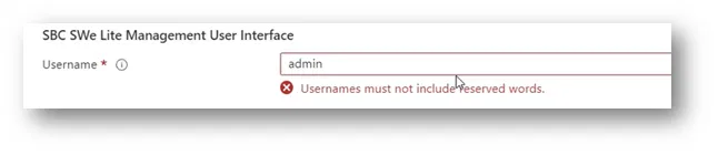
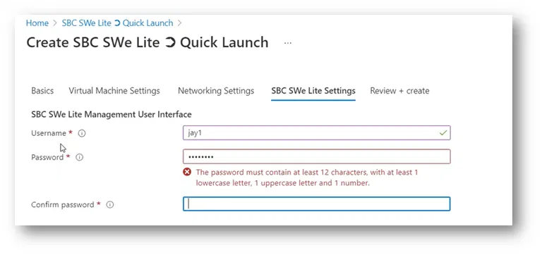
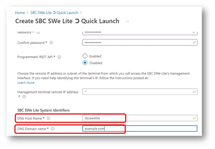
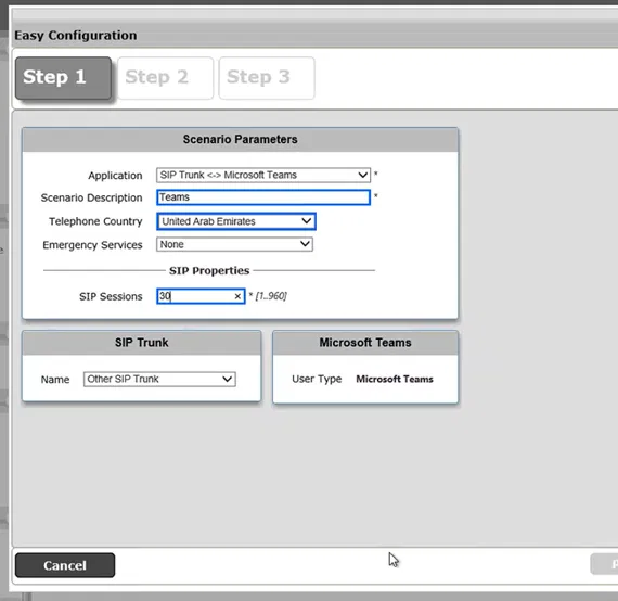
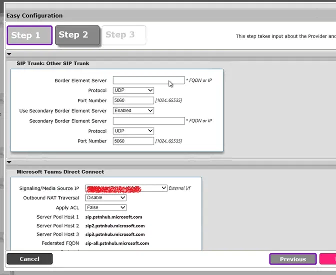
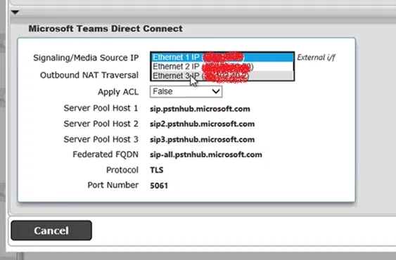
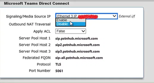
Filling “Configure CCE” Tab
In this tab, you will provide the VMs Name (and their IP settings), Hyper-V Host name and also mediation service Trunk Configuration
Note that, this tab will not be enabled unless the “CCE Public Certificate” is installed
The information in this tab will be used to fill the file CloudConnector.ini

Fill-in the information correctly, any changes in this configuration requires rebuilding CCE

The “External Network DNS” could be the DNS server of your service provider. You might also use Google DNS 8.8.8.8.
After filling the information, click on Apply
Note that, the fields will disappear, and you have to select the option “Click to re-configure CCE application” in case you want to change any settings.

You will also notice that the “Current Activity Status” shows that the update is completed

Prepare CCE Tab
Go to “Prepare CCE” tab
You will see the value of the fields that were filed under the previous tab “Configure CCE”

Scroll Down and click on Prepare CCE

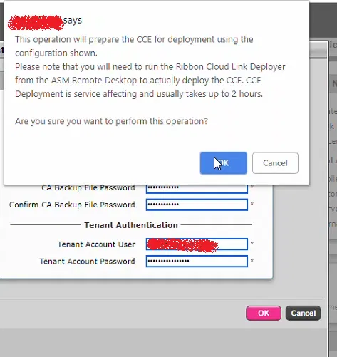
Fill in the needed passwords and click on OK
Don’t forget to note down the passwords you are filling here. All these passwords are new and will be used for your CCE VMs
“Tenant Account User” is any Global Admin of Office 365
This information will also go into CloudConnector.ini file
After filling the filed, click on OK

After clicking on OK on Enter Password box, you will get the following message
Read it and click on OK
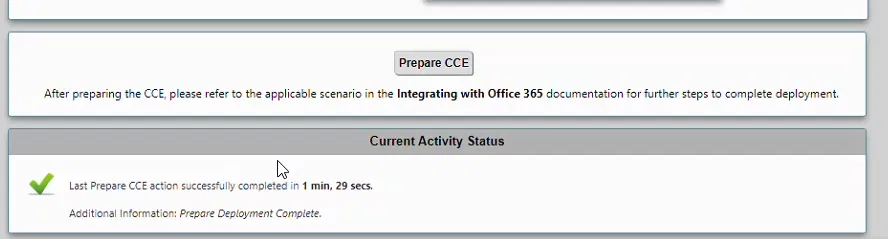
You will get the following message which indicates that operation is successful
Click on OK

However, if you get an error such as the following. You need to click on Prepare CCE again and fill in the passwords

If there are no problems, you will notice the progress of “Prepare CCE” operation under “Current Activity Status”

Wait until, “Current Activity Status” shows that the operation is successful
Changing the Administrator Password of CCE Host
This password is the Administrator Password for CCE Host which will be used to logging on
Note: the below images were captured using the old version of the firmware. The colors of the web interface are different. But the steps are the same. The reason is that I have acutely done it before upgrading the firmware
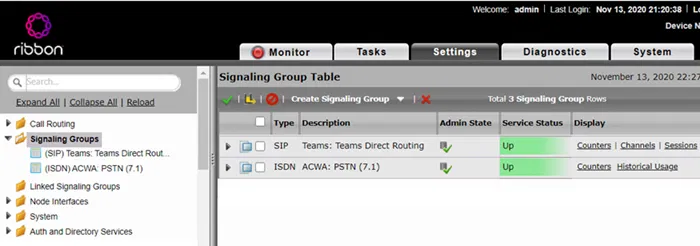
Click on Settings tab

The following image show how to Settings tab looks like

Expand “Application Solution Module”

Go to “Chance Admin Password”

Under “Password Option” setting, select “User Configured”

Specify the new password and click on OK

Under “Current Activity Status”, you will be prompt that the password is changed successfully

Logging on to CCE Host
Simply, using a Remote Desktop client, logon to the CCE Host using the IP address you have provided under the step “ASM Config tab” using the user name “Administrator” and the password you have provided in the step “Changing the Administrator Password of CCE Host”
Updating CCE Software
Before building CCE VMs, it is recommended to download and install the latest version of CCE software from Microsoft site. This will ensure that you are using the latest version of CCE
Download and install the latest version of CCE software from Microsoft site

Log on to CCE Host using Remote Desktop (check the steps under the section “Logging on to CCE Host”) and uninstall the existing CCE software using “Programs and Features” of Control Panel

Install the newly downloaded CCE software


Start PowerShell console as Administrator

Run the command Start-CCDownload

Wait until the command execution is finished

Running Cloud Link Deployer
At this is step will run the deployer. Which will build the actual VMs of CCE. This process might take a few hours and it depends on the speed of the internet. Remember that the Windows Hyper-V Host need to access the internet on port 80 and 443 and also needs to access DNS as mentioned in the section “Firewall Ports and Settings”.
Log on to CCE Host using Remote Desktop (check the steps under the section “Logging on to CCE Host”)
On the desktop of CCE Host open the file CloudLinkDeployer

The application “Cloud Link Deployer” starts

Make sure that you check the following actions/steps (these actions are going to be done by the deployer)
- Transfer Password from SBC: This step imports the password that has been set during the Preparing the CCE.
- Register Appliance: This step registers this new appliance on your Office365 tenant.
- Install Appliance: This step deploys the CCE
Click on Apply

This will start the process of building CCE VMs
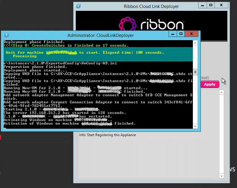
When the process is completed, the deployer will show the message “Notice: Completed the Cloud Link action” indicating that the process is complete

With this, you have the VMs of CCE installed and registered on Office 365
To Create a Dial Plan
In this step we are going to create a Dial Plan on Office 365. This dial plan will be used to normalize the numbers that are dialed by the users to E.164 format (adding + and country code).
The format used is like one used in the regular expressions of Skype for Business 2016 or Lync
The dial plan used in this example is for Dubai (UAE).
You first need to install the latest version of Skype for Business Online, Windows PowerShell Module which can be found over the net
Prepare PowerShell to get connected to Skype Online:
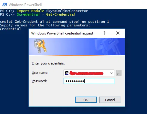
Import-Module SkypeOnlineConnector
$credential = Get-Credential
And type the user id and password of and Office 365 Tenant Admin
Run the following commands to complete the preparation of PowerShell console:
$session = New-CsOnlineSession -Credential $credential -Verbose
Import-PSSession $session -AllowClobber
Before you begin, check the existing Dial Plans
Get-CsTenantDialPlan
You should see the Initial Dial Plan which is named GLOBAL. You should not see any other Dial Plan (unless there is a Dial Plan that was created by someone else inside Office 365 Tennent)
To Create a new Dial Plan with the Name DXB-DP
The following will create an empty new Dial Plan:
New-CsTenantDialPlan -Identity DXB-DP -Description “Dubai Dial Plan” -SimpleName “DXB-DP”
To Create the Voice Normalization Rules to be added the Dial Plan
The following are the normalization rules to be added to the dial plan
$nr1 = New-CsVoiceNormalizationRule -Identity DXB-DP/Mobile -Description “AE-DXB-MOBILE” -Pattern ‘^0(5\d{8})$’ -Translation ‘+971$1’ -InMemory
$nr2 = New-CsVoiceNormalizationRule -Identity DXB-DP/Local -Description “AE-DXB-LOCAL” -Pattern ‘^0(4\d{7})$’ -Translation ‘+971$1’ -InMemory
$nr3 = New-CsVoiceNormalizationRule -Identity DXB-DP/National -Description “AE-DXB-NATIONAL” -Pattern ‘^0(\d{8})$’ -Translation ‘+971$1’ -InMemory
$nr4 = New-CsVoiceNormalizationRule -Identity DXB-DP/International -Description “AE-DXB- INTERNATIONAL” -Pattern ‘^00(\d+)$’-Translation ‘+$1’ -InMemory
Add the first normalization rule to the dial plan
Set-CsTenantDialPlan -Identity DXB-DP -NormalizationRules $nr1
Add the remaining normalization rules
Set-CsTenantDialPlan -Identity DXB-DP -NormalizationRules @{Add=$nr2}
Set-CsTenantDialPlan -Identity DXB-DP -NormalizationRules @{Add=$nr3}
Set-CsTenantDialPlan -Identity DXB-DP -NormalizationRules @{Add=$nr4}
To check the content of our new Dial Plan:
Get-CsTenantDialPlan -Identity DXB-DP
To check the normalization rules inside the Dial Plan:
(Get-CsTenantDialPlan -Identity DXB-DP).NormalizationRules | ft Name, Pattern,Translation, Description
Enabling Users
To enable users using PowerShell, you first need to install the latest version of Skype for Business Online, Windows PowerShell Module which can be found over the net
Prepare PowerShell to get connected to Skype Online:
Import-Module SkypeOnlineConnector
$credential = Get-Credential
And type the user id and password of and Office 365 Tenant Admin

Run the following commands to complete the preparation of PowerShell console:
$session = New-CsOnlineSession -Credential $credential -Verbose
Import-PSSession $session -AllowClobber
To Check the settings of existing User:
Get-CsOnlineUser -Identity user1@example.com
Or simply
Get-CsOnlineUser user1@example.com
To enable a user
The following 3 lines, will enable one user
Set-CsUserPstnSettings -Identity user1@example.com -HybridPSTNSite SITENAME -AllowInternationalCalls $true
Set-CsUser -Identity user1@example.com -EnterpriseVoiceEnabled $true -OnPremLineURI “tel:+9714XXXX1234;ext=1234” -HostedVoiceMail $true
Grant-CsTenantDialPlan -Identity user1@example.com -PolicyName Tag:DXB-DP
Note that the user should exists on Office 365 and has the proper licensing
You can put these commands in a script that read a *.csv file to enable multiple users
Explaining the commands
The first command assigns a Hybrid PSTN Site to the user and allow international call
If you don’t want to enable the user to make international calls, set -AllowInternationalCalls to $false in the first for the first command. The full command would be:
Set-CsUserPstnSettings -Identity user1@example.com -HybridPSTNSite SITENAME -AllowInternationalCalls $false
SITENAME is the name of the “CCE Site Name” that was used in the step “Filling “Configure CCE” Tab”
The second command, enable Enterprise Voice for the user which, assign a phone number (from DID range). The phone number is E.164 format (the example is for Dubai UAE). The command also enable Voice Mail for the user
Finally, the third command assigns a Dial Plan for the user. In this example we are assigning the dial plan that was created in the section “To Create a Dial Plan”
To change user telephone number
Set-CsUser -Identity user1@example.com
-OnPremLineURI “tel:+9714XXXX1234;ext=1234”
To get information about user
Get-CsOnlineUser user1@example.com
To Disable International Calling (for a user):
Set-CsUserPstnSettings -Identity user1@example.com -AllowInternationalCalls $false
To Enable back International Calling (for a user):
Set-CsUserPstnSettings -Identity user1@example.com -AllowInternationalCalls $True