After configuring Direct Routing with Local Media Optimization, you need to check that Local Media Optimization is working correctly
One way to verify that Local Media Optimization is working correctly is to check the headers in the invite SIP message to examine whether the headers contain the correct values.
Tool Used to Capture SIP Messages (LX Tool from Ribbon)
Ribbon SBC Edge family of products sends the logs using the Syslog protocol.
These logs can include SIP messages and other types of logs depending on the level and settings of logging.
To capture the logs from my Ribbon SBC 1000 (a member of the SBC Edge family), I am using the LX Tool from Ribbon to capture the SIP messages
The LX tool captures the logs by acting as a Syslog server to capture the logs.
After capturing the logs, I have used this tool to verify the header of the invite message
Teams Client Detects That It Is External
When Teams Client is inside the internal network, but the Direct Routing with Local Media Optimization is not configured correctly (or the Teams Client is external)
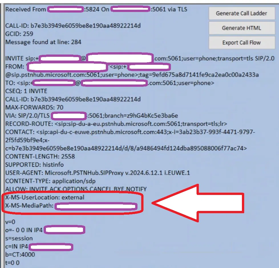
The X-MS-UserLocation header is set to external. In the invite message (as the image below shows)
X-MS-MediaPath is set to the SBC FQDN (this is a single SBC setup)
Note:
When Teams Client is really in the external network, the X-MS-UserLocation is set to external (which is the correct setting)
The image below shows the invite message between Teams Client and Ribbon SBC 1000 captured using the LX tool (Ribbon tool to capture Syslog we discussed above). The headers mentioned above are in a red box.
Teams Client Detects That It Is Internal
When the Teams client is inside the internal and Direct Routing with Local Media Optimization is configured correctly,
The Invite message will have the X-MS-UserLocation header set to internal.
X-MS-UserSite header will appear in the invite message and will be set to the site of the Teams Client
X-MS-MediaPath is set to the SBCs FQDN in the correct order (In the example below, X-MS-MediaPath shows only one SBC, since we have only one SBC in our setup)
The image below shows the invite message between Teams Client and Ribbon SBC 1000 captured using the LX tool. It contains the three headers we mentioned (The headers are in a red box)
You can use Local Media Optimization with a single site with a single SBC only. This is useful for keeping media traffic inside the internal network (without using Media Bypass). In a previous post, I explained how to configure such a setup using PowerShell. In this post, I will show how to do such configurations using the Teams Admin Center.
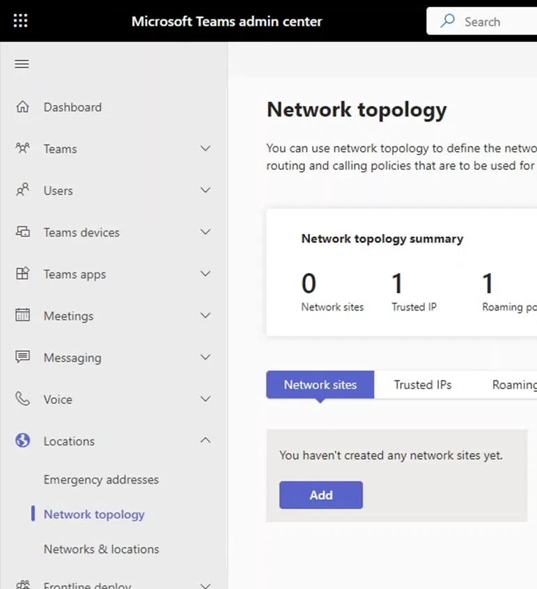
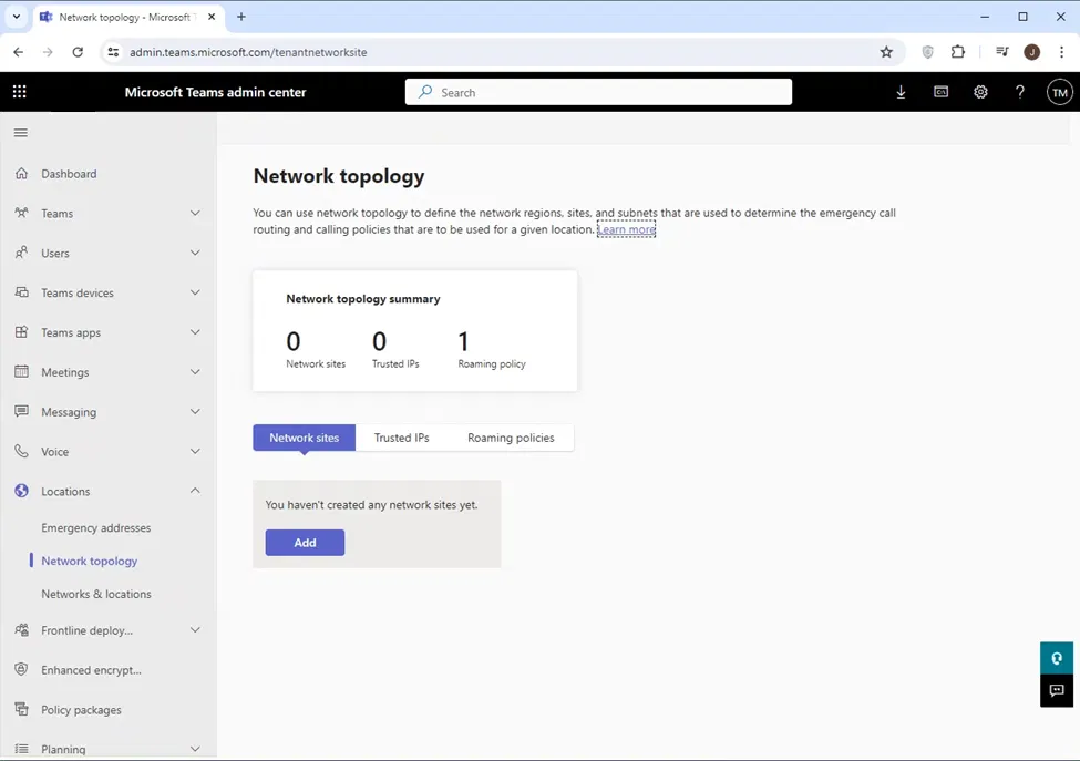
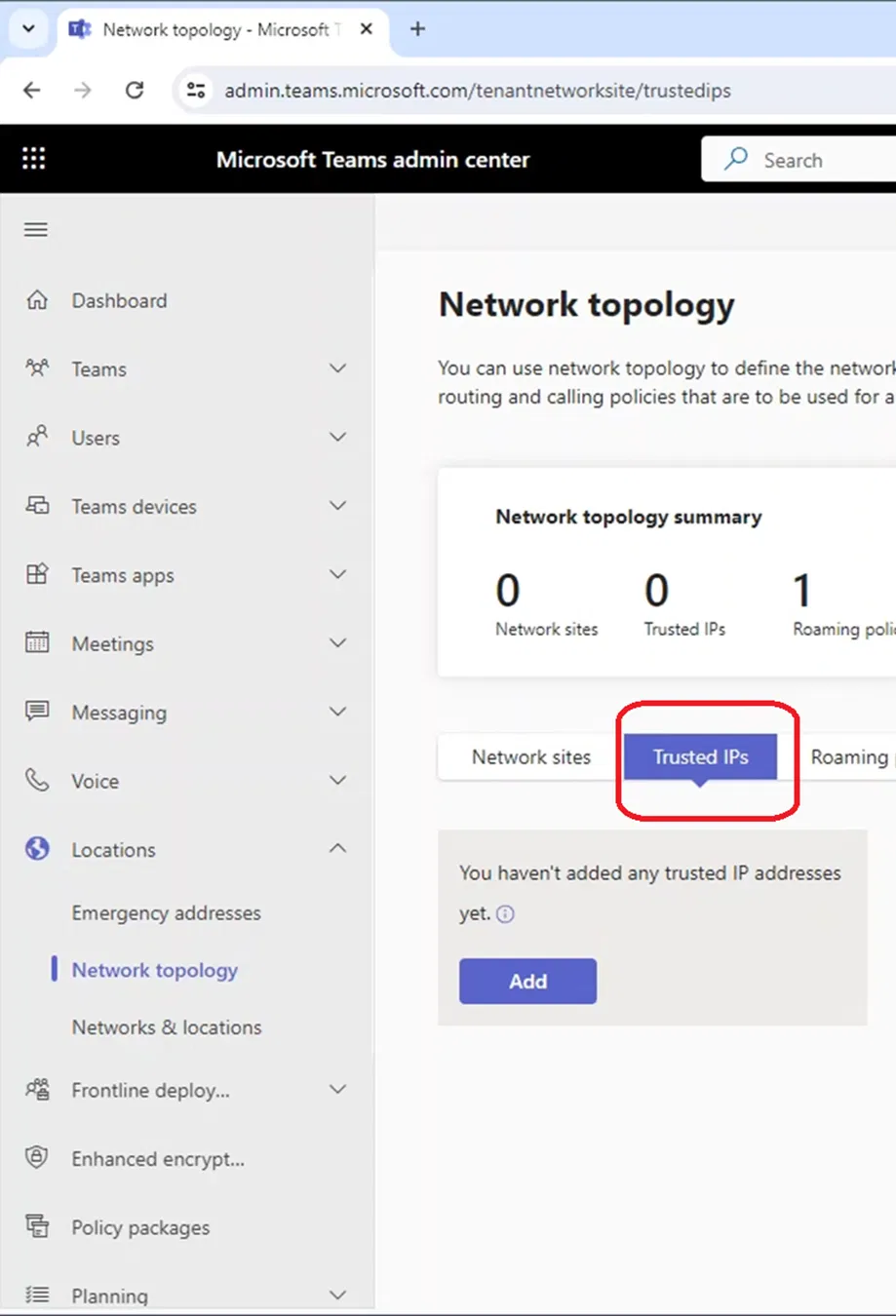
Configuring Trusted IP, Region, Site, and Subnet is done under the Network Topology page.
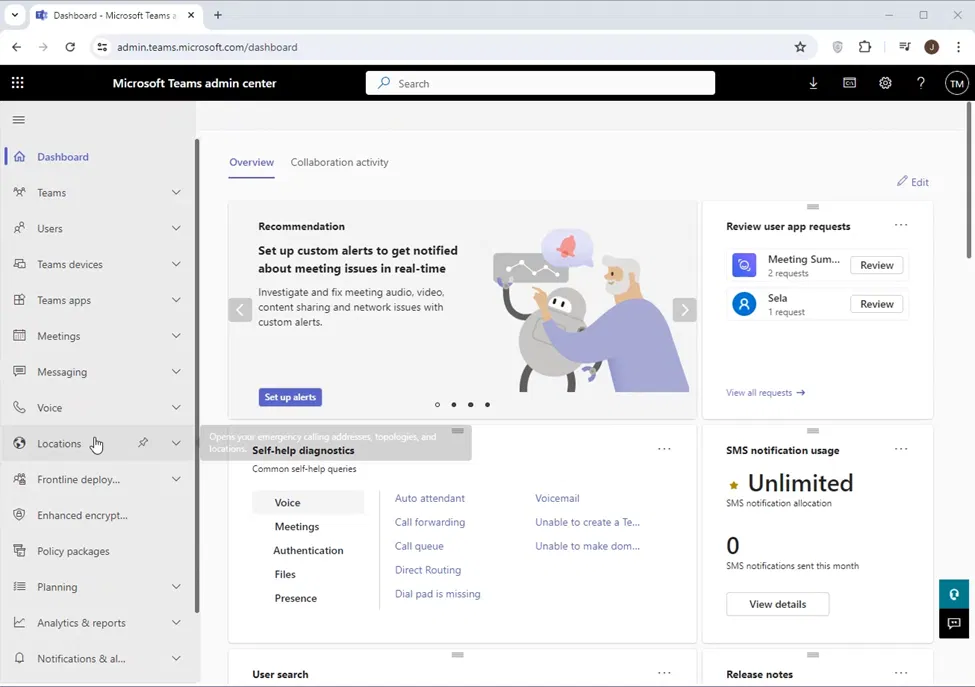
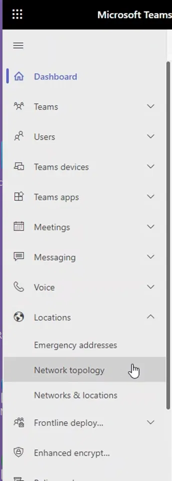
Network Topology page can be accessed through Teams Admin Center > Location > Network Topology.
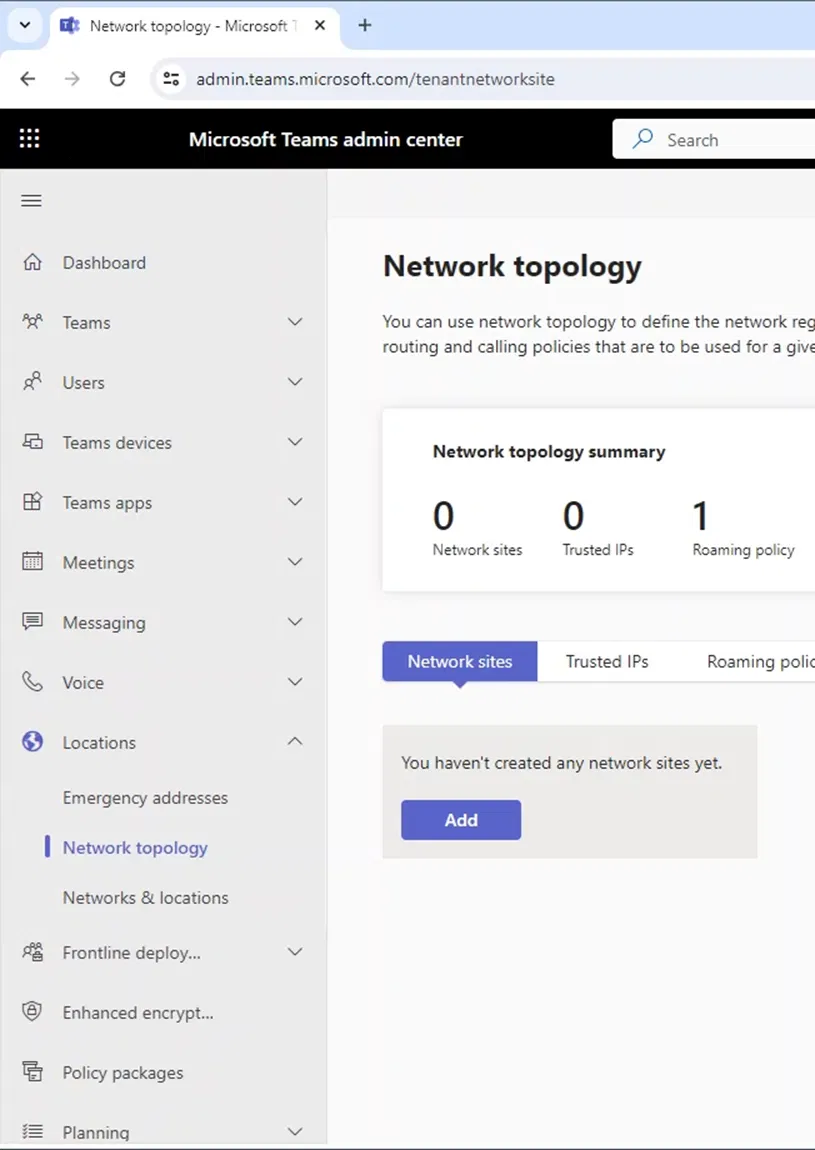
Go to Location > Network topology.
The following shows the Network topology page.
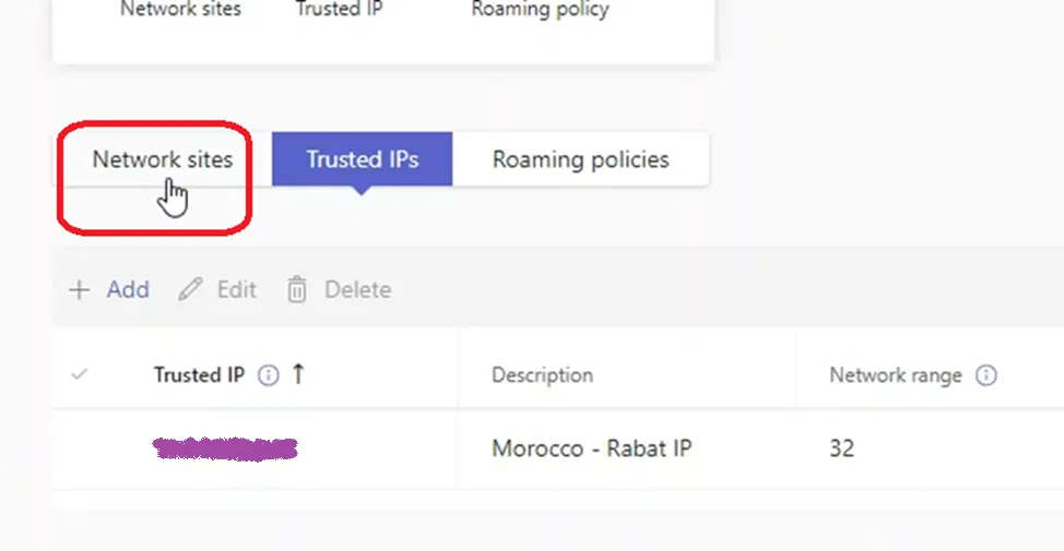
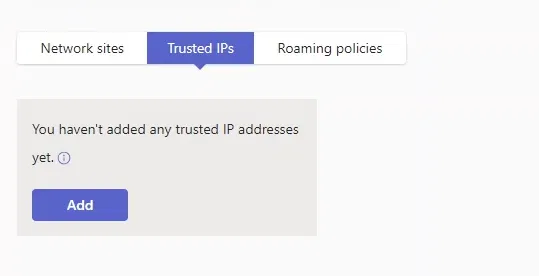
Adding a Trusted IP
Trusted IP is the fixed IP that clients use to access the internet. It is used by Teams to determine if the client is inside the internal network. Local Media Optimization will be utilized by the client when it determines that it is connected to Microsoft servers using a Trusted IP. If you cannot have a fixed IP to access the internet, you will not be able to configure a Trusted IP and in this case you can use Local Media Optimization.
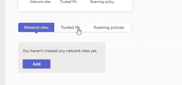
To configure a Trusted IP, on Teams Admin Center go to Location > Network topology and click on Trusted IPs
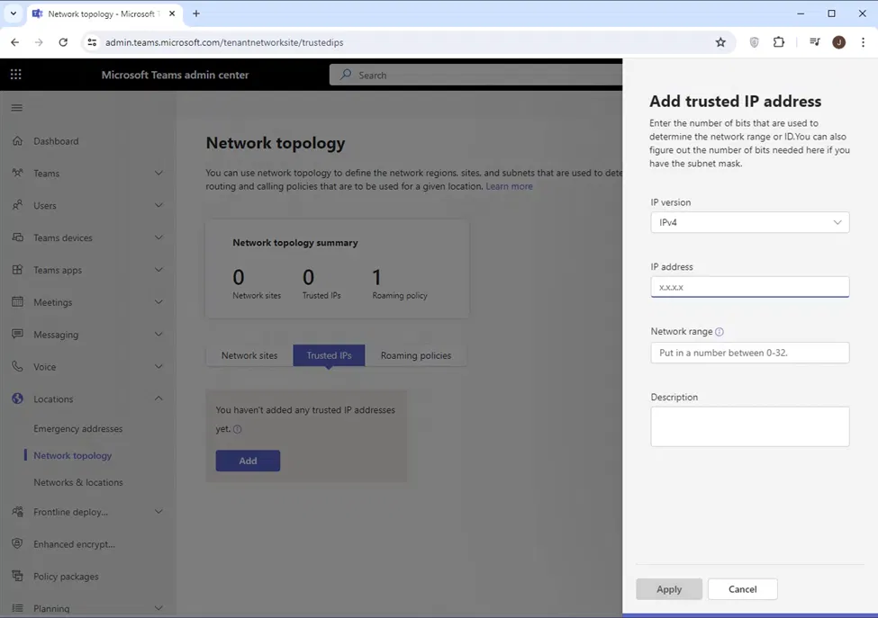
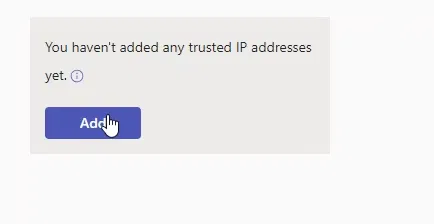
Click on Add
`
The “Add trusted IP address” pane will appear on the right side
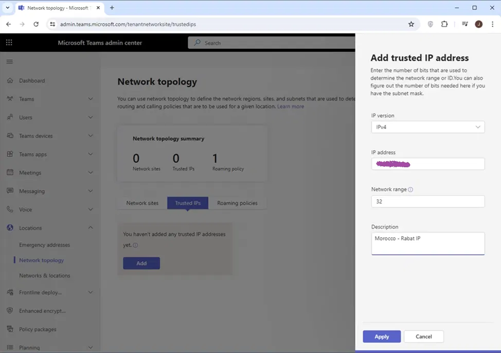
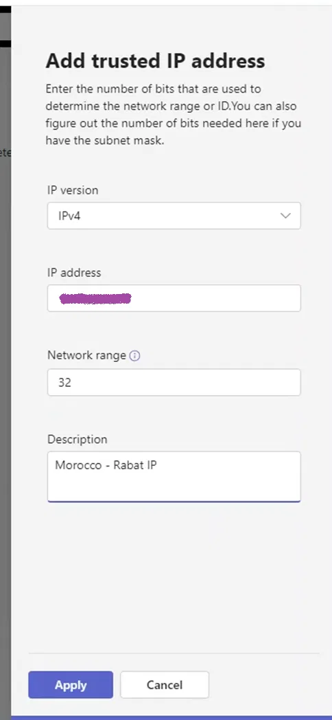
Add the IP address, network range (number of network bits), and description for this IP. Note that the network range is 32 if it is a single IP (which is more of the cases)
Click on Apply
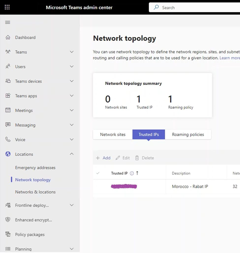
The newly configured Trusted IP will be under the list of Trusted IPs
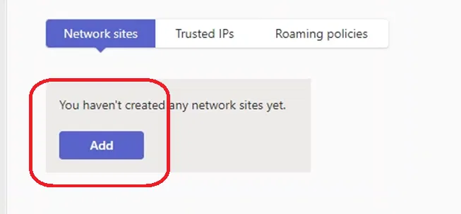
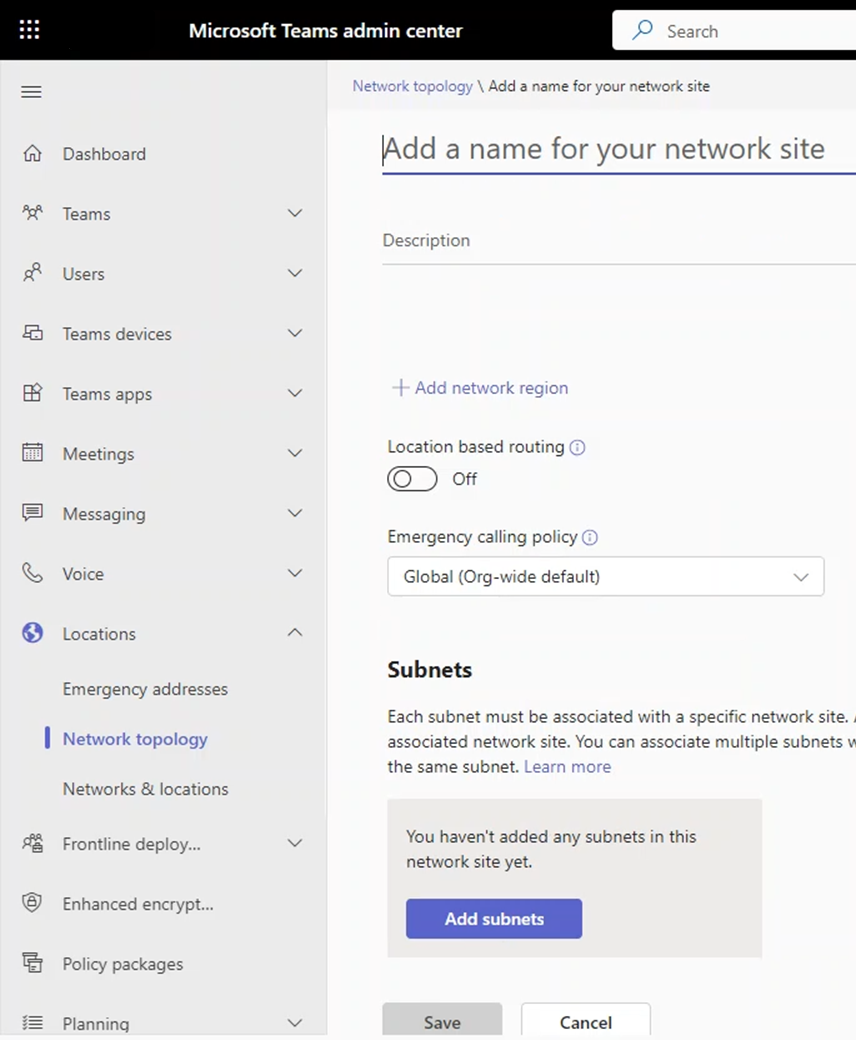
Adding and a Network Site
When Teams Client stats and it notices that it is internal (communicating with Teams servers using a Trusted IP), it will try to determine to which sites it belongs to (by checking it is in one of the subnets of that site)
To configure a Trusted IP, on Teams Admin Center go to Location > Network Topology, and click on “Network sites”
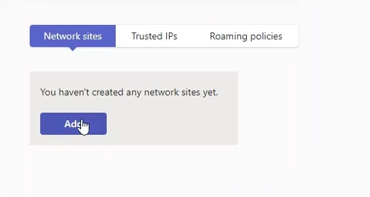
Click on “Add”
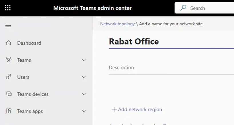
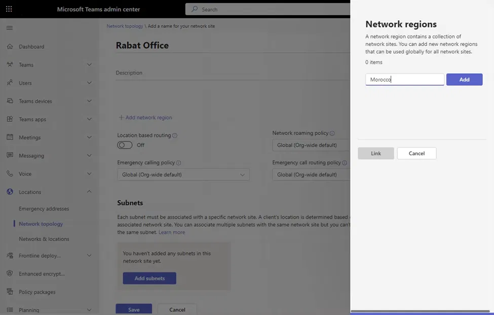
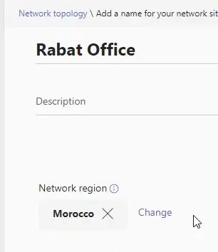
Type the name for the network site you ar creating
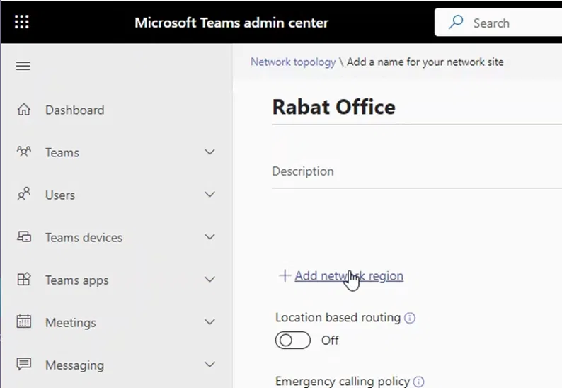
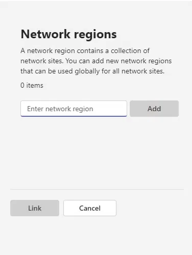
Adding A Region and Linking It to The Site
Each site should belong to a region. A region is a geographical location that contains multiple site. You can associate the site you are creating to a region or add a new region as shown below
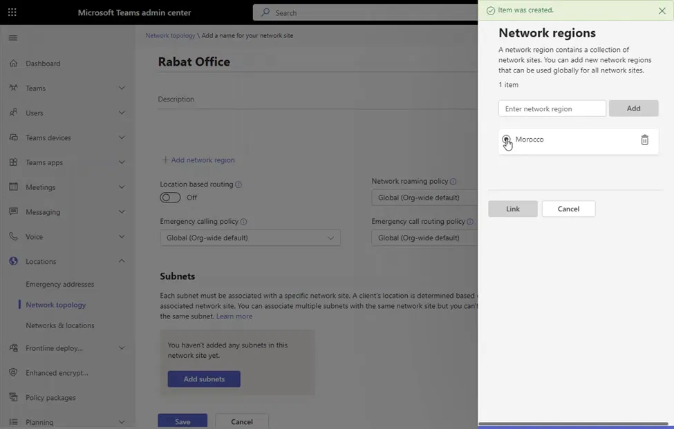
To add a new region to the network site, click on “+Add network region”
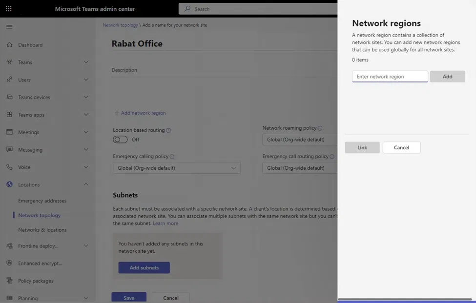
The “Network regions” pane will appear on the right side
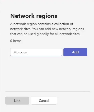
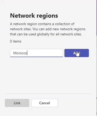
Type the name of the region
Click on “Add”
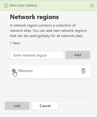
After that, you will see the name of the newly added region. Click on it to select it (this is the list of all network regions in the environment)
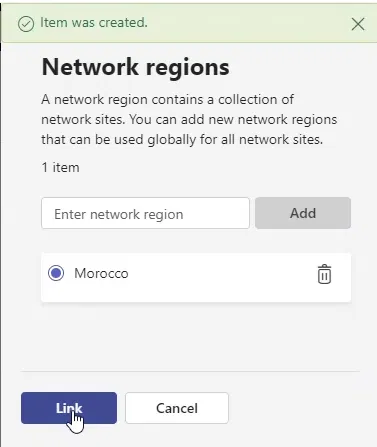
After making sure that you have selected the region, click on “Link” and that will link your site to the region and close the “Network regions” pane
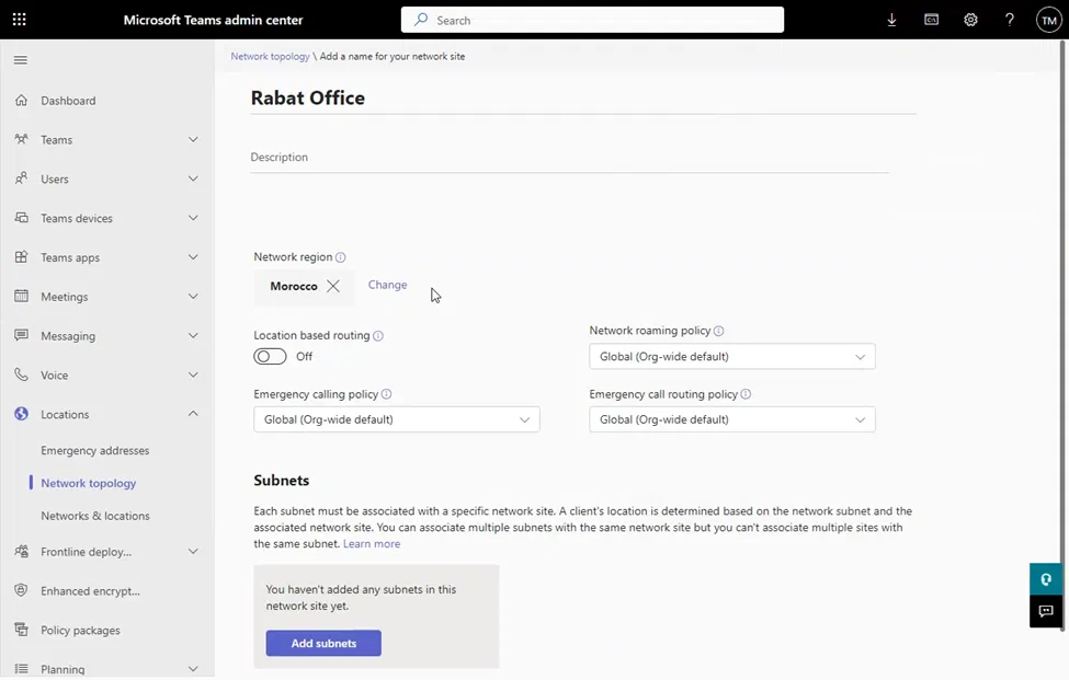
The newly linked network region will be shown under the details of the site
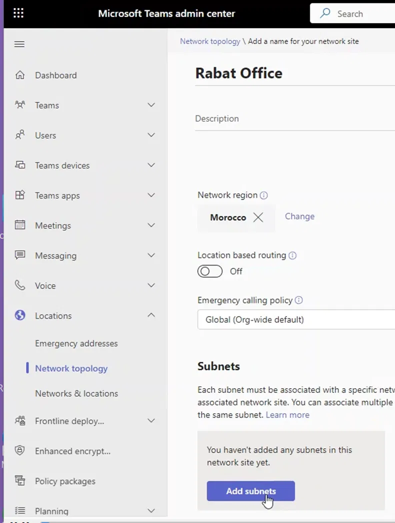
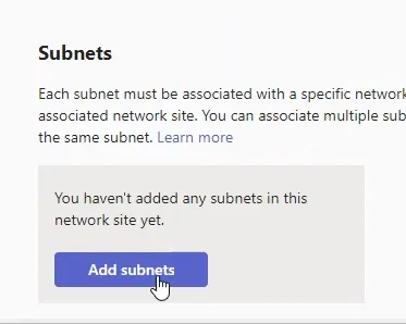
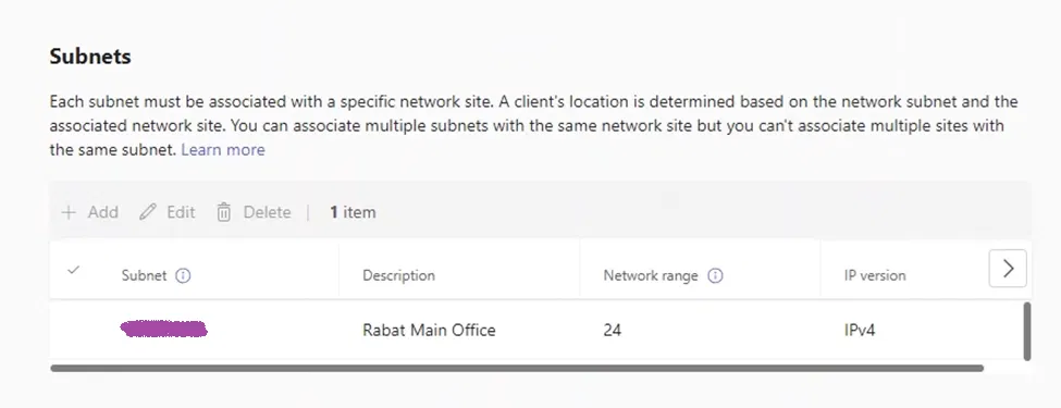
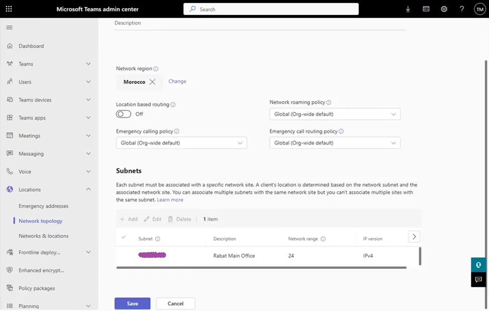
Adding a Subnet to The Site
Each site has subnets that belong to it. When a Teams Client starts and finds out that it is internal (based on Trusted ID), it will try to search to which subnet it belongs, and from that it will determine to which site it belongs
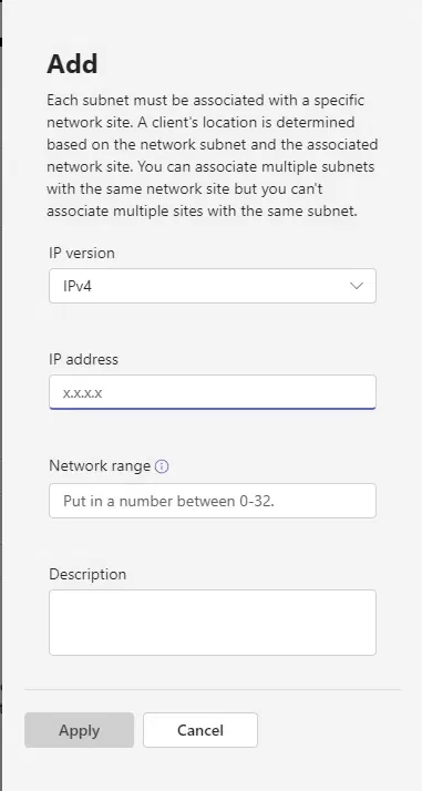
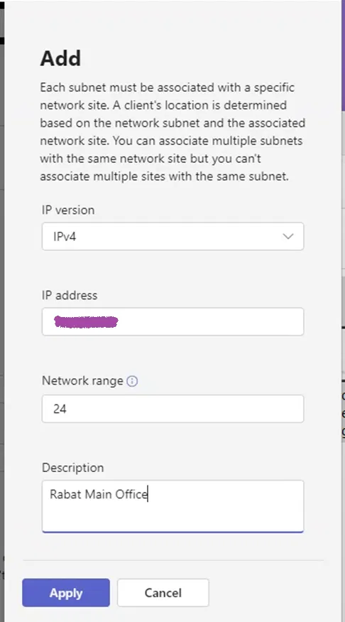
On the site properties page, under “Subnets”, click on “Add subnets”
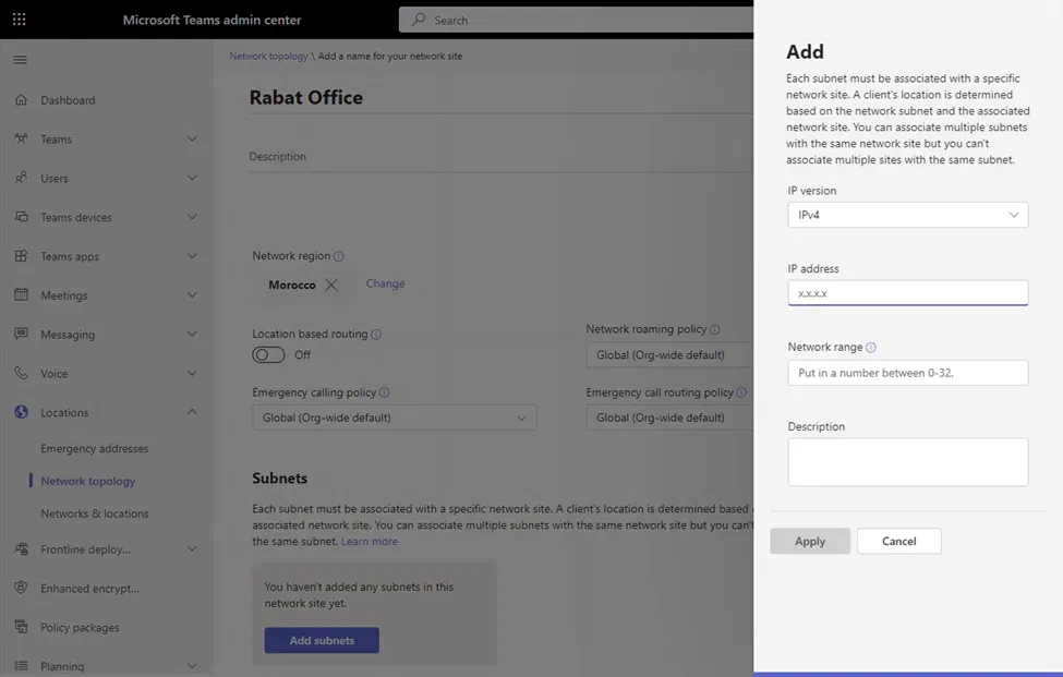
A pane will appear on the right side that allows you to add a subnet
Add the IP address, network range (number of network bits), and description for this subnet
Click on Apply
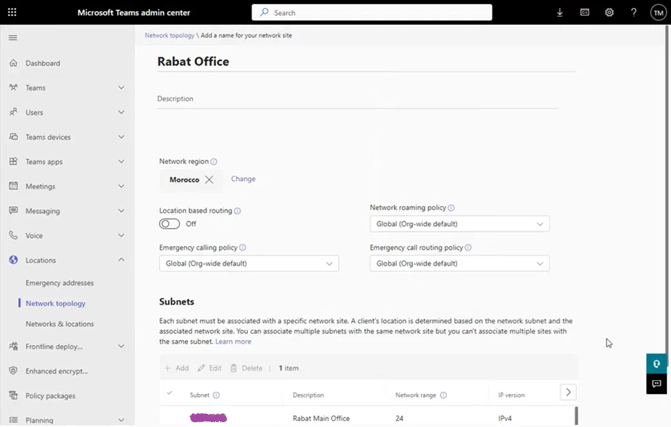
The site properties page will show the newly added subnet
Click on “Save” on the Site properties page
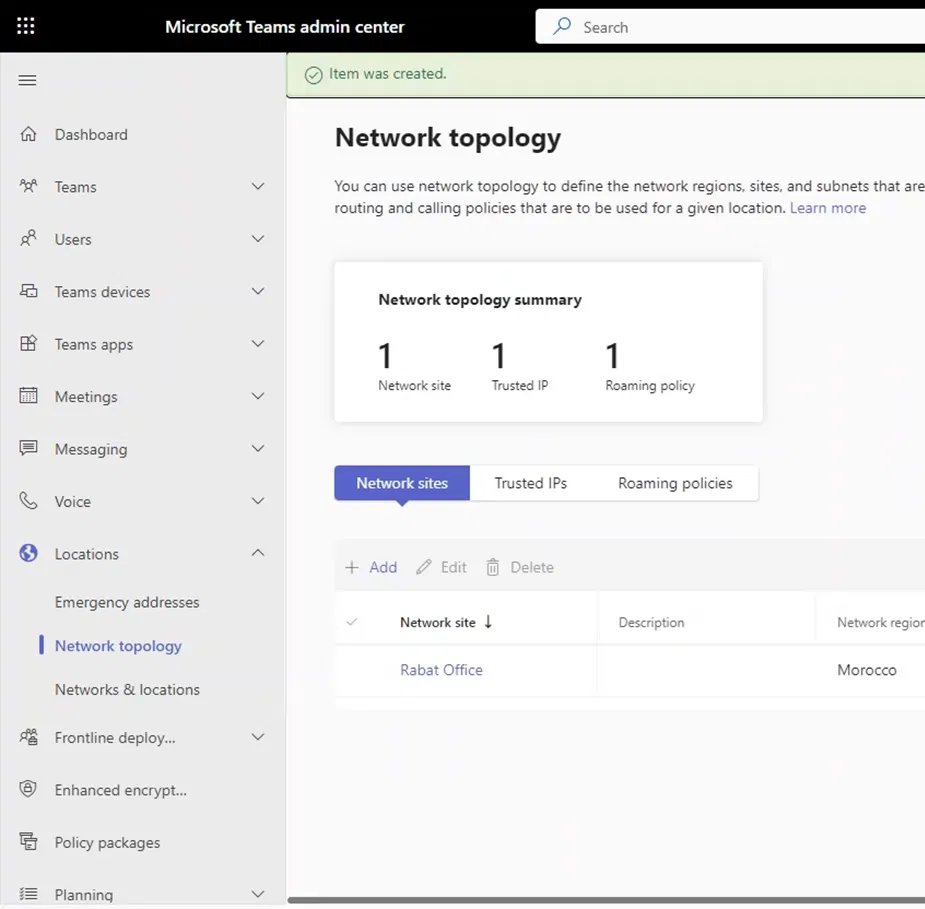
You will get back to the main Network topology page and it will show the newly created network site
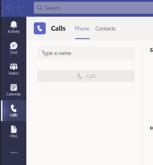
You can use Microsoft Teams Client to test the Auto Attendant or the Call Queue without the need to use the telephony (PSTN). With this method, you bypass the telephony (PSTN) settings. This is useful if you are unsure if the issue is with Auto Attendant / Call Queue or with the telephony settings such as the SBC Gateway. Or even the telephony settings are not configured or implemented yet.
I am illustrating these steps with elaboration and using detailed screen captures.
Calling Auto Attendant or the Call Queue Using Teams Client
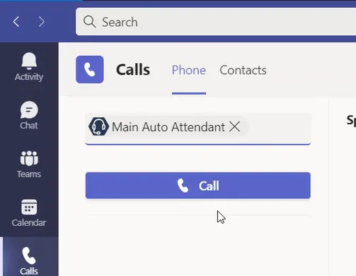
On Teams client, go to the “Calls”
Select “Type a name” box
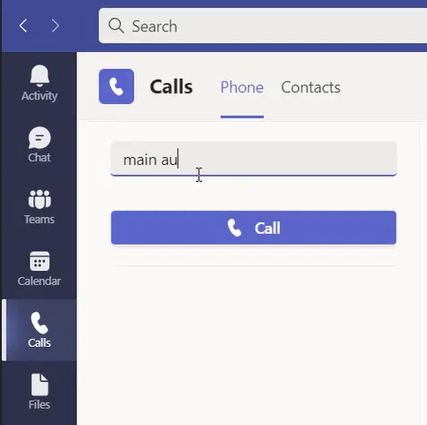
Type the name of the Auto Attendant or the Call Queue you want to test or type the first few letters of its name
The full name of the Auto Attendant or Call Queue will appear below the “Type a name” box
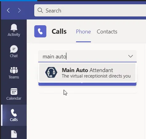
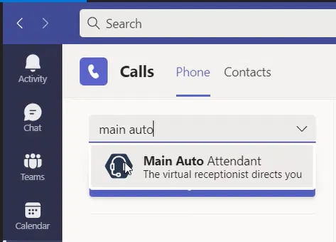
Select the name of the Auto Attendant or Call Queue
The name of the selected “Auto Attendant or Call Queue” will appear under the “Type a name” box which means you can call it
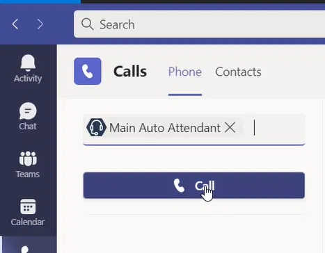
Click on the “Call” button
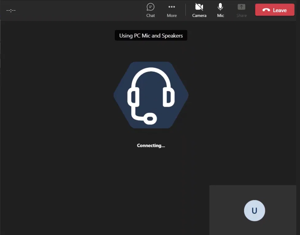
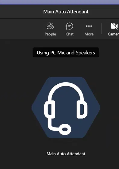
A new window will show you the call to that “Auto Attendant or Call Queue”
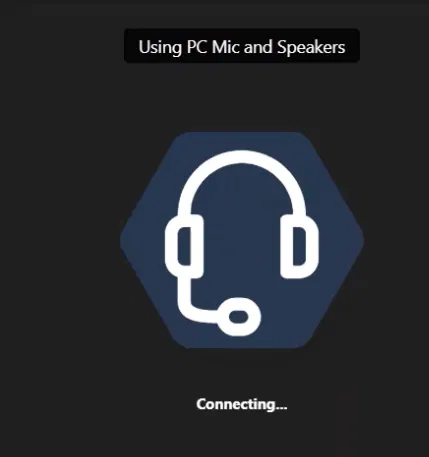
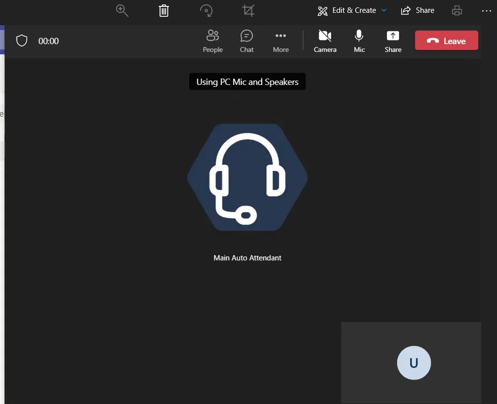
It will start with “Connecting” like any other regular call as the image below shows
The blow shows a connected call to the Auto Attendant
You should be able to hear the greeting message and menu options message on your PC
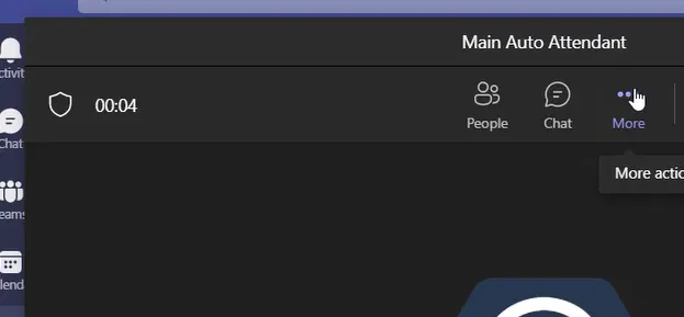
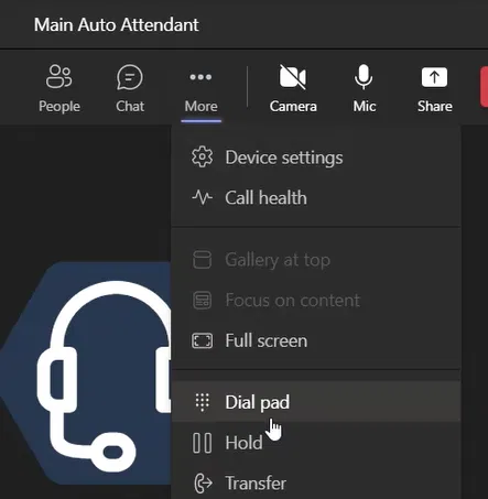
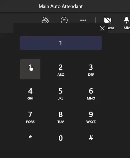
Accessing Dial Pad
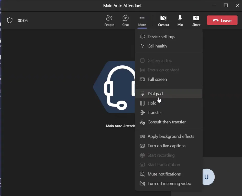
In order to access the dial pad to select the menu option, on the call window, click on more as the image below shows
Under the menu that appears, select “Dial pas”
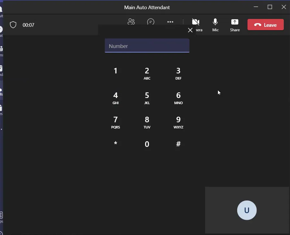
The dial pad will appear
Click on the dial pad to select the option you want to access
If you are using Ribbon SBC Edge (SBC 1000 / SBC 2000 / SBC SWe Lite) that is integrated with Teams Direct Routing, you noticed on your SBC Edge repeated warnings/errors under the Alarm View on the Monitor tab like the following:
SIP-TLS Server Handshake Failure
SIP-TLS Handshake Negotiation Start Failure
You might have different causes of the alarm (the cause is inside the description of the alarm)
Reason for these Warnings and Errors:
The reason for these warnings and errors is that there are many machines on the net that keeps scanning SIP servers on well know SIP ports trying to hack them to make calls.
To avoid these machines from scanning your SBC, you need to limit SIP communication only with Microsoft Teams server (SIP Proxy) which consists of these two ranges (52.112.0.0/14 and 52.120.0.0/14) as explained in the link:
If your SBC is behind a firewall, you can simply configure the firewall to limit SIP communication to only (52.112.0.0/14 and 52.120.0.0/14)
Using SBC Edge Access Control List (ACL)
Another method is to utilize applying Access Control List (ACL) on the “Logical Interface” of SBC that is connected to the internet.
You can create your own ACL or you can utilize the existing ACL created by running “Easy Config Wizard” and selecting Teams as a scenario
Notes About Using Access Control List (ACL):
You need to allow HTTPS allowed on the interface to control the SBC if you have the same interface for both managing the SBC and for SIP and Media communication
If you configured allowing HTTPS incorrectly in the ACL, you will lose access to the Web Interface of the SBC
It is better to have an additional interface enabled with the correct IP and connected to the network. This would help in case you have applied an ACL that is incorrectly not allowing HTTPS. This way, you will not end up with your SBC Web Interface inaccessible
In the case of SBC 2000, the Admin Port is usually configured by default and has the default IP of 192.168.128.2.
It might be confusing to find the ports required for Teams Media Bypass. Especially, since you need to check different Microsoft documentation and SBC documentation
This article explains the needed firewall ports and why we need them. And I will explain how to find the needed media ports for Ribbon SBC Edge.
Although Local Media Optimization (LMO) might better option than Media Bypass, LMO does not support Teams SBA (Survivable Branch Appliance). In such a case, Media Bypass is a good option to use.
Another reason to choose Media Bypass is that it might be easier for you to implement it over implementing implement LMO.
Type of Teams Calls Traffic
The following are the two types of Teams Calls traffic including Teams Direct Routing
Signaling Traffic:
Traffic that is related to the control of the call such as call initiation and call ending. Such traffic is not heavy, but it is important for the call.
Media Traffic
This traffic contains the actual voice that can be heard during the call. It is heavier and it requires to be delivered with less latency and with the shortest path if possible.
The above two types of traffic are explained in the link:
Teams Direct Routing Call Traffic without Media Bypass
In Direct Routing without Media Bypass, both signaling, and media traffic is from Teams Client to Microsoft Servers to the SBC to PSTN and vice versa (Teams Client <-> Microsoft Servers <-> SBC)
Teams Direct Routing Call Traffic with Media Bypass
With media bypass, the media traffic for Teams telephony is between the Teams client and the SBC (Teams Client <-> SBC) while signaling remains the same (Teams Client <-> Microsoft Servers <-> SBC)
In other words, with Teams Direct Routing the voice traffic is between Teams Client and SBC without sending it to Microsoft Servers
Refer to the following Microsoft article for more details:
In the above table, I have put port 5061 as the signaling port for SBC. Port 5061 is the default port used for Signaling when using Easy Configuration Wizard of Ribbon Edge. This port can change while running the wizard or after completing the wizard (by changing the resulting “Signaling Group”)
Media Ports Between the SBC and Microsoft Servers
Even though you have configured your SBC with Media Bypass, you need the media ports for non-Media Bypass for a situation such as:
The Public IP of the SBC is not accessible for some reason. In this case, Teams Client will fail over to non-Media Bypass communication
The administrator chooses not to allow access to the Public IP of the SBC other than Microsoft Servers (maybe for security reasons)
There are some Teams Clients that are not capable to support Media Bypass (such as the old 3PIP phones)
In such cases, the media traffic will be without Media Bypass (Teams Client <-> Microsoft Servers <-> SBC)
Under the section “Requirements for using Transport Relays”
For how to find the exact Media Ports on Ribbon Edge SBC, check the section “How to Find and Set the Media Port Range on SBC Edge” section below
Media Ports Between SBC and Teams Clients (Internal Network or Internet)
These are the ports that are used for Media Traffic of Media Bypass for both internal clients and internet clients. This traffic is between the SBC and the Teams clients on (Internal Network or Internet)
Under the section “Media traffic: IP and Port ranges” and subsection “Requirements for direct media traffic (between the Teams client and the SBC)”
For how to find the exact Media Ports on Ribbon Edge SBC, check the section “How to Find and Set the Media Port Range on SBC Edge” section below
How to Know the Media Ports for Ribbon SBC Edge (SBC 1000 / SBC 2000 / SBC SWe Lite)
Below is how to find the media ports for the Ribbon Edge family of SBCs. These ports are mentioned in Microsoft documents as “Defined on the SBC”
How to Find and Set the Media Port Range on SBC Edge
On the Web Interface of the SBC, go to
Settings tab > Media > Media System Configuration
Under the “Port Range” section, you will set the starting port and the number of ports
Regular Call Media Port Range will be from the “Start Port”
And it will calculate the port ranges for you. There will be two port ranges, one is for regular media and the other is for ICE.
The port range that you need to allow on the firewall is from the “Regular Call Media Port Range” to the last port of the “ICE Call Media Port Range”
The following image shows the UDP Media Ports is from 1024 to 1824
Default Media Ports Range for each of SBC Edge models
For each model of the SBC Edge, there is a different range of ports that is already set (you can change it as explained in the section above). The following is a table with the default port range for each module.
Module
SBC 1000
SBC 2000
SBC SWe Lite
Media Port Range
UDP 17586-21186
UDP19386-28386
It depends on the Media Port paired configured in the SBC
Under the section “Configure SBC when Microsoft Teams is in Media Bypass Mode”
The link above also explains how to disable Media Bypass on Ribbon SBC Edge
Teams Signaling Group Created with Old Version of Easy Configuration Wizard (Old Firmware)
If your Teams signaling group was created with old version of easy setup wizard (old firmware), the Signaling Group might not be enabled for Media Bypass. In that case, you can enable it by following the same link:
Notes About Configuring Media Ports Opened Correctly
The firewall and other network devices need to be configured correctly to allow bi-directional communication between the internal clients and the public IP of the SBC on the specific ports for each direction
The ports from the client to the public IP are different from the ports from the public IP to the clients
In case of the failure of media communication between Teams Client and the public IP of the SBC, the media communication will go through Microsoft Servers (Teams Client <-> Microsoft Servers <-> SBC). The user might notice a slight delay in establishing the call.
In case of the public IP is NATed to an internal IP of the SBC, the internal clients need to have bi-directional communication with the Public IP itself and not the internal IP of the SBC.
When using NATing, outgoing traffic should always go through the public IP specified for the SBC. Many firewall devices are configured to use their default shared IP instead of the specific IP for the SBC. That causes a problem in the configuration because Microsoft Servers are expecting the traffic to come from the public IP that is mapped to the SBC.
Use network packet capturing and analyzing tools such as WireShark to verify that the media traffic is between Teams client and SBC and not between Teams client and Microsoft Servers
Port from Internal Clients (Internal Network) to Microsoft Servers
You need to check the article and links before you start your implementation. Microsoft keeps changing the required ports and IP addresses needed for Teams communication.
You must use the last parameter -PhoneNumberType DirectRouting since you are using Direct Routing. Otherwise, Set-CsPhoneNumberAssignment command let will fail.
The Old Parameters
When we were using the old command Set-CsUser, we used to use the following two paraments:
-EnterpriseVoiceEnabled $true
-HostedVoiceMail $true
Enterprise Voice Enabled
Regarding the “Enterprise Voice Enabled” flag, it will be set to true automatically when you set -PhoneNumber to the phone number of the user
But right now, with Set-CsPhoneNumberAssignment, there is no need to use these two parameters (provided that you are using -PhoneNumberType DirectRouting)
Hosted Voice Mail
Regarding Hosted Voice Mail flag, according to the documentation of Set-CsPhoneNumberAssignment, setting HostedVoiceMail for Microsoft Teams users is no longer necessary.
One of the common issues when configuring Local Media Optimization is that the Teams client is not detecting that it is inside the internal network. In this article, I am explaining how to check the logs to see if the Teams Client knows that is internal.
The reason for the client not knowing that it is internal is that it doesn’t find its own Public IP in the list of Trusted IPs (the list is configured on the tenant). And that makes it behave as if it is external and not internal (when a client starts, it will detect its Public IP and compares it to the list of Trusted IPs).
Since the client thinks that it is external and not internal it will not try to connect to the internal interface of Central SBC or downstream SBC at its site for media traffic. Instead, it will try to pass the media traffic through the Public IP of the SBC of the Central SBC or Proxy SBC. Finally, when that connection is not passable, it will try to connect to Microsoft Phone System (Teams servers on the cloud).
Based on my experience, even if you have configured the Trusted IP correctly on the tenet, it takes some time for that change to be reflected on the Teams client. (Although Microsoft documentation says it requires 30 minutes or just restarting the client will make the change to be reflected)
Usually, I don’t enable Local Media Optimization on the SBC device until I am sure that the clients are detecting that they are coming from a Trusted IP by checking the logs (as explained below)
Below I am explaining how to check the logs to verify that the client is detecting that it is coming from a Trusted IP.
Downloading the Logs
To download the logs of Teams Client, click on the keys Ctrl + Alt + Shift + 1 together while Teams client is in focus
On the right side of the screen, you will see some messages that indicate that the downloading started
Opening the log file
To access the log files, open the “Downloads” folder on the computer
Inside it, you see a folder that started with MSTeams Diagnostics Log [Date]__[Time]_
Inside it, you will find a folder named “web”. Open the “web” folder
You will find some logs files, open the file that ends with the word “calling” the file name will be in the format MSTeams Diagnostics Log [Date]__[Time]_calling.txt
Checking The Contents of The Log File
This is how the file would appear
The log file shows Public IP detected doesn’t match any Trusted IP
The following is the log file section that shows that the client’s public IP is detected and it also shows that this IP doesn’t match any of the IPs of the trusted IP list (“reason”: “NotMatched”)
The log file shows that Public IP is matching a Trusted IP
The log file is showing public IP is matching the Trusted IP (“reason”: “Matched“) and it also shows the detected Network Site. With this, we are sure that the client detected that it is internal, and it is ready to utilize your Local Media Optimization settings
In this article, I am showing how to configure Local Media Optimization for Single Site with Single SBC which is good for:
Simply keeping the media traffic inside the internal network
To avoid sending the media traffic between the internal network and the public IP address (usual configuration of Media Bypass)
Avoid the complex configuration of the firewall
Most of the documents available right now are explaining how to configure Local Media Optimization for multiple sites and it might be hard to figure out how to just simply configure LMO for a single site
Creating a Trusted IP
The trusted IP is the Public IP that your internal clients are using to access the internet. It is the IP that is configured on the NAT setting on your firewall. You might find this IP by searching “what is my IP” on the web browser of your client. But it is better to get the help of the network team or security team. After all, they are the ones who have configured the firewall.
When Teams client starts up, it will contact Teams servers and if the client is connecting these servers using a Trusted IP, the client will be considered as internal, and the client will try to determine to which site it belongs to. During the PSTN calls, the media traffic will be travel between the client and the internal IP (Signaling/Media Private IP) of the SBC (PSTN Gateway).
If the client connects Teams servers using a Public IP that is not in the list of Trusted IPs, it will consider itself as an external client. And in that case, the media traffic (the voice) will be between the Public IP of the SBC (PSTN Gateway) and the client.
Notes:
When the client is accessing the internet from an IP that is not in the list of Public IPs, after it considers itself as external (as explained above), it will try to access the public IP of the SBC (PSTN Gateway). The thing to watch for is that it is not possible in most cases because the firewall will not allow such traffic.
(From what I have seen, if the firewall is not allowing such traffic, the call will ring normally, but the moment the call is answered, the call might not get established or there is a delay in establishing the call)
The clients might be using different Public IP to access the internet. In that case, you need to add all these IPs as Trusted IPs
The following command shows how to add one Trusted IP:
New-CsTenantTrustedIPAddress -IPAddress x.x.x.x -MaskBits 32 -Description “City1 Public IP”
(In the example above, I am putting the IP as x.x.x.x as an example. Replace it with your trusted public IP)
Creating a Region
A region is defined in Microsoft documentation as “A network region contains a collection of network sites. It interconnects various parts of a network across multiple geographic areas”. You can define your region as a country, part of a country, or any sort of geographical area. Sites always need to belong to a region.
The following command shows how to define a region:
When Teams client designates itself as internal (after the client starts up, it will try to determine to what site it belongs to (it checks if it belongs to the subnets of that site).
And based on the Bypass mode settings of the SBC (PSTN Gateway) (the settings of the SBC that are defined on the Tenant), the client will send the media traffic internally or to Teams servers (explained below in the section “Creating Subnets and Associating them with a Site”).
The following command shows how to define a new site and to which Region it belongs too:
When Bypass Mode is set to Always, even if they are not in the same site as the SBC (PSTN Gateway), the internal client will always try to establish media traffic with the internal IP of the SBC (PSTN Gateway)
If Bypass Mode is set to OnlyForLocalUsers, the internal client will establish media traffic with the internal IP of the SBC (PSTN Gateway) only if the internal client is at the same site as the SBC (PSTN Gateway). If the client is not in the same site as the SBC (PSTN Gateway), the Media Traffic will be with Teams Servers.
ProxySbc Mode Parameter
ProxySbc is set to $null because we are using Single Site and Single SBC. $null means that this SBC is not a “downstream SBC”.
If you want to only configure your SBC as a standalone SBC (Single Site – Single SBC), you don’t need to worry about the option of LMO while running the wizard. You simply need to complete the Easy Config Wizard with the Teams Direct Routing option (without selecting Local Media Optimization options when running the “Easy Config Wizard”). After that, you add the configuration for Local Media Optimization as I am showing below.
I Usually Complete Implementing Teams Direct Routing First
What I usually do during my implementations is that I complete configuring, testing, and troubleshooting of Teams Direct Routing without Local Media Optimization (Usually, I face issues, especially with firewall settings). After verifying that Direct Routing is working fine, I add the settings related to Local Media Optimization
Network Interfaces Needed
You need to have two network interfaces:
One network interface for “Signaling/Media Private IP”
Additional network interface for “Private Media Source IP”
Usually, you already have a network interface for “Signaling/Media Private IP” that is enabled for the command Teams Direct Routing. You need to enable an additional network interface “Private Media Source IP”.
Steps To Add “Local Media Optimization” To an Existing Setup
The following is how to modify an existing Teams Direct Routing Configuration to make with Local Media Optimization with one SBC (not Proxy SBC nor “Teams Downstream SBC”)
On the Settings tab, expand Signaling Groups
Expand the “Teams Direct Routing” Signaling Group (this is the usual name that is created by Easy Config Wizard)
Scroll down until your reach the “SIP IP Details” section
Under “Teams Local Media Optimization”, select “Enable”
Under “Signaling/Media Private IP”, make sure that the network interface that is facing the internet is selected (used to get connected to the internet, the same subnet as the Default Gateway and has the Public IP mapped to it)
Under “Private Media Source IP”, make sure that the network interface that is facing the internal network is selected (you need to remember to add a route to the internal network that goes through the gateway of the subnet of this IP)
Scroll down and click on Apply
This is how the “SIP IP Details” section of the Signaling Group would appear after completing the configuration
With Teams Direct Routing and Microsoft UC in general, there is no 4 digits extension or 3 digits extension by default. However, all organization usually used to using a 3 or 4 digits extension assigned to each user. Especially the ones that got migrated from another telephony systems to Teams Direct Routing.
In this article, I will show how to support these short digits extension with Teams Direct Routing. This is achieved by adding a Normalization Rule to the Dial Plan that is used by the user. This rule will transform the 3 or 4 digits the user is dialing to a full E.164 format that matches the usual format of the LineURI for user.
This will work because the 3 or 4 digits extension number is usually the last part of the DID number.
Creating a New Dial Plan
In case you don’t have a dial plan ready to have the normalization rule, you need to create a new dial plan as follows:
New-CsTenantDialPlan -Identity JaysLab -Description “Dial Plan for Jay’s Lab” -SimpleName “JaysLab”
Creating a New Voice Normalization Rule
This is the Normalization Rule that will change the 4 digits that a user dials to a E.164 format. The rule adds the leading common digits of the LineURI of the users (proceeded by +). In my case, the leading digits are +1712458
Adding the New Normalization Rule to the Dial Plan
The created Normalization Rule above needs to be added to the Dial Plan. This Dial Plan could be a newly created one. Or it could be an existing one that is already assigned to users. The below shows adding the Normalization Rule to the Dial Plan that was created earlier in this article
This is the test part. The below image show dialing the 4 digits extension
After a few moments Teams will automatically find the user that has that full number, and you can click on it and select it
The below image shows the user is selected and ready to be called
You can even see the details of that user by hover the mouse over the username before dialing as the image below shows
You can click the “Call” button to call that user. The following image shows the established call with the user (it looks exactly similar if you have called that user without dialing the 4 digits)
Alternatively, you can dial the 4 digits number and click on the “Call” button without selecting the user. This is useful if you are sure of the extension number and you want to call it directly.
If you call the user directly, the full E.164 number will be shows at the top the call while in the middle it will show that you are calling the user as the image below shows
User 1 which is the called one, the call pop up appears as any normal call

 `
`